Managing Project Changes Between the Schematics and 3D Design Phases
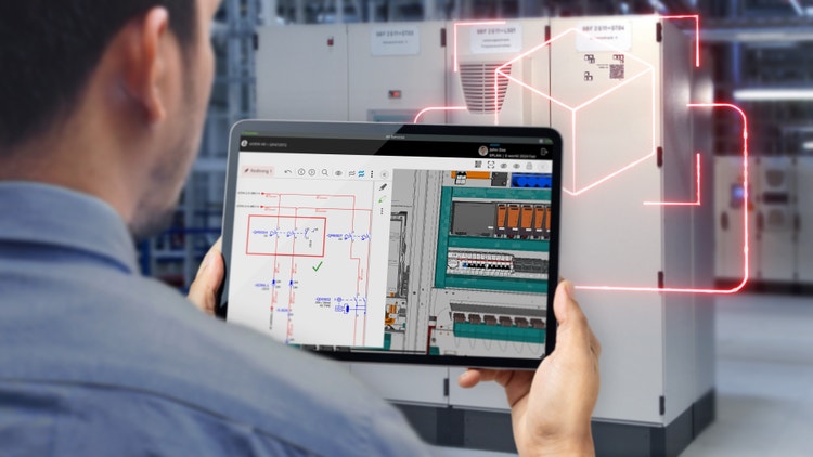
In this situation, there is no automated consistency check between the two environments. Discrepancies often go undetected until assembly or commissioning, where they surface as misrouted cables, missing terminals, or components that physically don't fit. These problems become far more expensive to fix at this stage, and the burden of keeping multiple documents aligned between the two systems falls entirely on the engineer's diligence and memory. As projects grow in complexity or involve multiple contributors, the likelihood of something falling through the cracks increases significantly.
While other processes become mired in situations like these, this is where the integrated Eplan workflow shines. Our system is highly interconnected throughout the process, and this interconnection goes both ways: from schematic to 3D, and from 3D back to schematic management.
How Changes Work After Moving to 3D
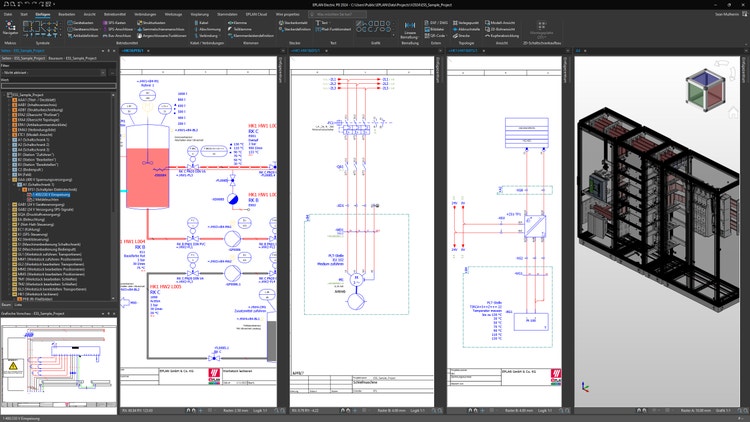
Once a project transitions from schematics built in Eplan Electric P8 to 3D design in Eplan Pro Panel, the system continues to maintain a live data connection between the electrical schematics and the 3D cabinet model. This means engineers are not locked into a "finished" schematic before beginning 3D work. The two representations share a common data model within the Eplan Platform.
When components or wiring are changed in the 3D model (e.g., repositioning a component on a mounting plate, rerouting a wire, or swapping out a device), the underlying project data is updated. Because the schematic and the 3D layout draw from the same dataset, changes made in the 3D environment are reflected in the schematics, and vice versa. This eliminates the traditional problem of schematics and physical layouts drifting out of sync.
Automatic Downstream Synchronization
A key capability is that last-minute changes to the wiring and routing in Eplan Pro Panel are automatically updated for processing in Eplan Smart Wiring. This means production-facing documentation stays current without any extra manual effort. When a component is swapped or wiring is rerouted in the 3D model, the system automatically recalculates:
- Wire lengths and routing paths based on the updated physical layout
- Cable duct fill levels to verify the new routing fits
- Drilling patterns and cut-outs for modified component placements
- Bills of materials, wiring lists, and terminal diagrams derived from the updated data
On the shop floor, Eplan Smart Production uses a traffic-light status system to show technicians exactly what has changed: items still to be completed are marked in red, completed items in green, and version-difference visibility highlights where changes have occurred since the last revision.
The Benefits of Eplan for Automation System Engineers
Here’s how engineers can work more efficiently, respond faster to late-stage demands, and deliver higher-quality results with confidence, all while keeping projects on track and production-ready.
- Single source of truth: Schematics, 3D layouts, and production documents all derive from the same project data, so a change in one place propagates everywhere automatically.
- Late-stage flexibility: Engineers can make design changes well into the 3D phase without manually reconciling schematics, reducing the cost and risk of late revisions.
- Reduced rework: Validation features like collision checks, mounting-clearance verification, and cable duct fill calculations catch problems in the digital twin before fabrication begins.
- Faster production handoff: Manufacturing documentation (wiring lists, drilling data, cut-out specifications) is regenerated automatically from the updated model, eliminating manual document updates.
- Shop floor transparency: Technicians always work from the latest data, with clear visual indicators of what has changed, reducing errors from outdated paper drawings.
- Cross-discipline coordination: DSE integration ensures that mechanical and electrical design stay aligned even when changes happen on either side.
Moving to Fully Synchronized Engineering, From Schematic to Shop Floor
Eplan empowers automation engineers to move faster, work smarter, and confidently adapt to change by connecting schematics, 3D design, manufacturing data, and shop floor execution into one intelligent engineering environment. Instead of losing valuable time to manual updates, disconnected systems, and costly late-stage errors, engineering teams can accelerate design cycles, improve collaboration, and deliver higher-quality control panels with greater efficiency with an integrated electrical engineering system.
Whether you are looking to modernize your engineering workflow, reduce rework, or create a true digital twin for panel design and manufacturing, Eplan provides the tools to make it possible. Contact us today to discover how our integrated solutions can help transform your automation engineering process and give your team a competitive advantage.